Learning Hardware Level 1:
Serial (UART), Breadboards, Basic GPIO r/w
Overview
This block is meant to help you get comfortable with two of your core interfaces in embedded systems: UART (or serial) and GPIO. It also introduces you to your best friend in prototyping: the breadboard. Almost every chip or MCU you will come across has GPIO pins and usually a basic LED connected on the board. Toggling a GPIO pin, or blinking an LED, is usually the introduction to almost any new hardware and sometimes your only debug output when hacking firmware on existing boards.Prerequisites
You will need the components listed here. You can order them from anywhere but be sure they are the same parts.You will also need basic competence in python, linux, SSH, and screen (or other serial terminal program) and a laptop or workstation.
Pre-Read Notes
You can experiment a bit with breadboard circuit design via online simulators. TinkerCAD is fairly friendly to use.Laptop <-> RPi Serial Communications
This guide will walk you through connecting and enabling serial (UART) communications between your laptop or workstaion, and the raspberry pi. Note that in the "Connect the Lead" section it highlights how you can power the RPi via the USB Serial cable itself. This works well for RPi Zero models but can be under-powered for RPi 4 or running power hungry peripherals.While the set-up above covers enabling the console over serial on the RPi for testing, you will want to disable console-over-serial before you begin the experiments. You will do this with the "raspi-config" utility by enabling the serial interface but disabling the console over serial. Remember to reboot the RPi after the change.
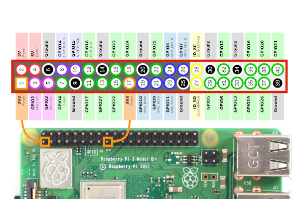
While we haven't covered the PiOLED display yet, if it is attached to the RPi, as seen here, you may need to use one of the other "Ground" pins available on the RPi shown below.
GPIO Write - toggle LED
First make sure the python GPIO library is installed:sudo apt-get install python-rpi.gpio sudo apt-get install python3-rpi.gpioThen follow this tutorial to set-up the breadboard and blink the LED via python code. It is worth remembering that the Raspberry Pi uses 3.3v logic on its GPIO pins, while Arduino boards use 5v logic, so your components for this exercise should be 3v. The core concept here is that GPIO pins, can be set in read or write modes, and, in basic terms, is nothing more than voltage being on or off.
Once you are comfortable with the above example, expand your code to read a command from the serial port, and set the GPIO pin in response. For example, if you loop and read the serial port, and when you receive the letter "h", set the GPIO pin to high or on. If you read the "l" character, set the GPIO pin to low, or off. Then connect the RPi serial to your laptop, open the screen terminal, and toggle the LED on/off.
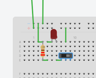
The next step is to test your hardware switch in this simple circuit. Add the hardware switch to the positive side of your circuit similar to the picture below. You should be able to set the GPIO pin to high, then turn the LED on or off by toggling the hardware switch that opens or closes the circuit.
GPIO Read - read state change
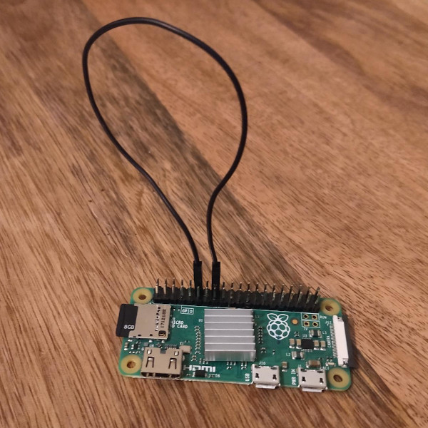
This experiment is very simple and does not even require a breadboard. It does, however, require two terminals into the RPi. The easiest path is simply two SSH sessions into the RPi. So you will need to enable SSH and have it network accessible.The circuit for this can simply be connecting one GPIO pin directly to another with a simple breadboard cable, as shown below.
In one SSH session execute the "gpio-get.py" code, and in the other execute the "gpio-set.py" code from below. The "get" program exits after 10 seconds, while the "set" code change the state of the pin for 1 second.
gpio-set.py
import RPi.GPIO as GPIO
import time

GPIO.setmode(GPIO.BCM)
GPIO.setwarnings(False)
GPIO.setup(18,GPIO.OUT)
GPIO.output(18,GPIO.LOW)
time.sleep(1)
GPIO.output(18,GPIO.HIGH)
time.sleep(1)
GPIO.output(18,GPIO.LOW)
gpio-get.py
import RPi.GPIO as GPIO
import time

GPIO.setmode(GPIO.BCM)
GPIO.setwarnings(False)
GPIO.setup(23,GPIO.IN)

last = ''
i = ''
max = 100
ct = 0
while True:
  i = GPIO.input(23)
  if last != i:
    last = i
    print(str(i))
  ct = (ct + 1)
  time.sleep(.1)
  if ct > max:
    break
As with the GPIO-write experiment, you can take this further by using the serial console to report or display the GPIO state changes, thus only needing one SSH window and one serial terminal. A very minimal example of GPIO-read-to-serial is as follows:
gpio-get-to-ser.py
import serial
import RPi.GPIO as GPIO
import time

GPIO.setmode(GPIO.BCM)
GPIO.setwarnings(False)
GPIO.setup(23,GPIO.IN)

ser = serial.Serial('/dev/ttyAMA0') # or /dev/serial0

last = ''
i = ''
max = 100
ct = 0
while True:
  i = GPIO.input(23)
  if last != i:
    last = i
    print(str(i))
    ser.write(str(i))
  ct = (ct + 1)
  time.sleep(.1)
  if ct > max:
    break
You may need to install python serial module:sudo apt-get install python-serial python3-serialIf needed, read the docs on python serial.